C-Arm System Assembly: Electrical Integration, Cable Routing and EMC Coordination
Key considerations for component integration, cable routing and EMC
Complete C-arm system assembly involves integrating the mechanical structure, generator, detector, electrical controls and image-processing components. Assembly planning should address component mounting, cable routing, movement clearance, enclosure fit and service access, while considering EMC requirements throughout the process. System-level EMC performance needs to be verified through testing of the final configuration under relevant operating conditions.
Start with the selected system configuration
Before assembling a complete C-arm system, confirm the source, detector, generator, electrical control and display configuration. Review component dimensions, weights, connector positions and installation requirements as needed. Integrated monoblock sources and separate generator and tube arrangements can require different interfaces and cable space.
Before assembly, the supplier and customer should confirm the component configuration, scope of supply and mounting interfaces. Dimensional information or installation diagrams can be used where needed to check compatibility. High-voltage component selection, protective measures and electrical safety requirements must be defined by qualified parties for the actual system.
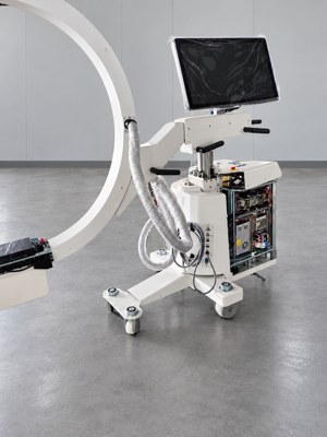
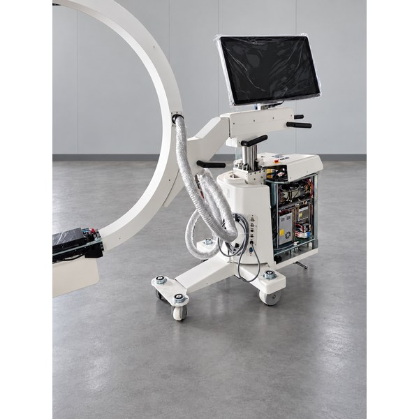
Figure 1. C-arm assembly in progress with the electrical compartment open.
Check cable routing through the intended movement
A cable route that fits while stationary may not suit the full operating range. During prototype assembly, review the agreed lift, rotation and other movements for pulling, pinching, rubbing and interference with moving parts. Use the final cable specification rather than assuming a temporary sample represents the production harness.
Confirm bend and twisting limits with the cable manufacturer. Identify fixed mounting points, moving sections, edge protection and replacement access. Record the approved routing in drawings or assembly instructions so later builds can reproduce it. LEONI describes cable routing development as a coordinated task involving mechanical components, electrical components and mobility models [1].
Coordinate electrical components with the mechanical layout
Customers can start by sharing the overall dimensions, mounting hole positions and connector locations of the electrical components they plan to install. Dimensioned drawings or DXF files can be provided where available. Kianzee can use this information to coordinate the internal mechanical layout, considering component mounting, cable routing and service access. Once the layout is prepared, we submit a structural layout drawing or installation diagram to the customer for review and confirmation, then adjust it based on their feedback.
Review electrical mounting and service access
Check that brackets, mounting plates and cable openings match the electrical layout. Allow the agreed space for connector installation, cable support, cooling provisions and maintenance. Access should remain practical after neighboring components and covers are fitted.
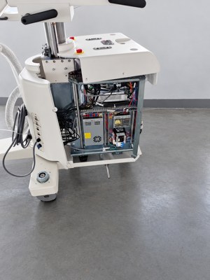
Figure 2. Open electrical compartment showing component mounting and visible wiring.
Coordinate the top cover with the internal layout
The top cover should be reviewed with the controls, handles, fasteners and internal components it surrounds. Check alignment, clearance and removal access before releasing the cover design. Confirm that fitting the cover does not trap cables or interfere with the approved layout.
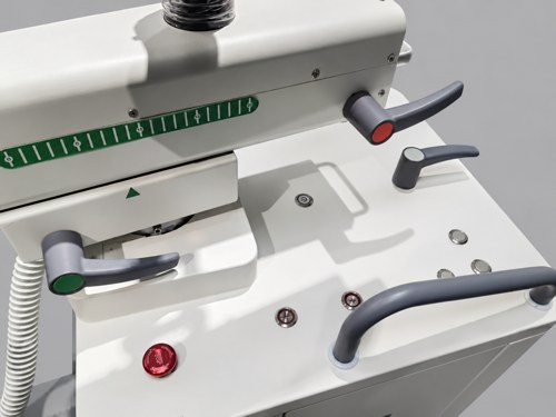
Figure 3. C-arm top-cover assembly showing controls, handles and adjacent mechanical parts.
Define EMC provisions before finishing
The OEM electrical and EMC teams should specify any bonding points, shield interfaces, conductive contact areas and required enclosure provisions. Translate those requirements into controlled drawings and finishing instructions. Where a conductive contact area is specified, masking or another agreed finish may be needed; Protocase describes masking as a way to keep selected areas free from insulating finishes [2].
A metal enclosure does not automatically establish adequate shielding or EMC performance. Do not improvise grounding, cable separation distances or shielding details from a photograph. Protective earthing and EMC bonding also need coordinated review against the applicable safety requirements.
Separate assembly checks from EMC testing
Mechanical checks can confirm fit, movement clearance, cover removal and specified cable supports. EMC concerns emissions and immunity of electrically powered equipment in its electromagnetic environment [3]. Assembly photographs show visible construction; they do not establish test results.
The OEM and its test laboratory should agree the applicable requirements, operating modes, accessories and cable configuration. Keep the tested configuration traceable to the production design. If changes are made during testing, document them and review their effect on safety and performance. FDA guidance discusses the assessment and documentation of EMC-related modifications [4]. Requirements for a particular destination market must be confirmed for that project. Final equipment integration, testing and applicable approvals remain the responsibility of the equipment manufacturer and its appointed parties. Local assembly and installation require suitably qualified local parties.
Discuss your C-arm project with Kianzee
Kianzee supplies C-arm mechanical structures and can coordinate component packages, including generators, detectors, electrical controls and image-processing components, according to project needs. The configuration, scope of supply and mounting interfaces are confirmed for each project.
Whether you are developing a new system or sourcing components, share your planned configuration, required components and quantity, together with any available dimensional information or installation diagrams. For custom mechanical parts, relevant manufacturing drawings can be reviewed at the next stage. We can discuss the supply scope and next steps together.
Contact: [email protected]
Related C-arm products
C-Arm X-Ray System OEM Component Package
C-Arm Mechanical Frame Buying Guide
Technical references
[1] LEONI — Cable system design for medical devices
https://leoni-healthcare.com/en/products-services/services/cable-routing/
[2] Protocase — Masking
https://www.protocase.com/products/finishes/masking/
[3] FDA — Electromagnetic Compatibility
Open FDA EMC overview
[4] FDA — Electromagnetic Compatibility of Medical Devices guidance
Open FDA medical device EMC guidance